Category: Electronics

  • Audio box toy

    For Christmas, I wanted to create a special homemade toy for my one-year-old daughter. I remembered seeing an article some time ago about someone making a wooden box toy for their niece, which played songs uploaded as MP3 files. I decided to adapt this idea and create a similar toy using 3D printing.

    The concept is straightforward: a large red button that, when pushed, triggers a microcontroller to play an MP3 file through an amplifier and a speaker (I chose a 2W speaker).

    In my initial prototype, I used two AA batteries, but they didn’t seem to provide enough power to the microcontroller to drive the audio speaker effectively. So, I purchased a cheap 5000 mAh powerbank. I attempted to power the USB port using the powerbank, but it wasn’t sufficient either. As a last resort, I opened up the powerbank and soldered the internal LiPo battery directly to the VSYS pin of the WeAct Studio RP2040. The battery now lasts for about 4 days, but this introduced a new problem. To charge the LiPo through the powerbank’s USB-C port or to use the USB-C port on the RP2040 to change the MP3 song, I needed to desolder the LiPo again, otherwise risking damage to the RP2040. To address this issue, I installed a small on-off slide switch between the battery and the VSYS pin of the RP2040. This allows me to disconnect the battery from the microcontroller and use the USB-C port on the powerbank for charging, or the RP2040 USB-C port to change a song.

    To create the MP3 files, I used Audacity to select a suitable section of a song, roughly 10 seconds long. I then applied an “Amplify” effect to decrease the volume. The required decrease varied depending on the song, ranging from -7dB to as much as -18dB.

    Since there are no ports on the outside of the box, I wanted to make the screw holes reusable. To achieve this, I used threaded heat-set inserts from CNC Kitchen. With a special soldering tip, it’s easy to install them into a 3D print.
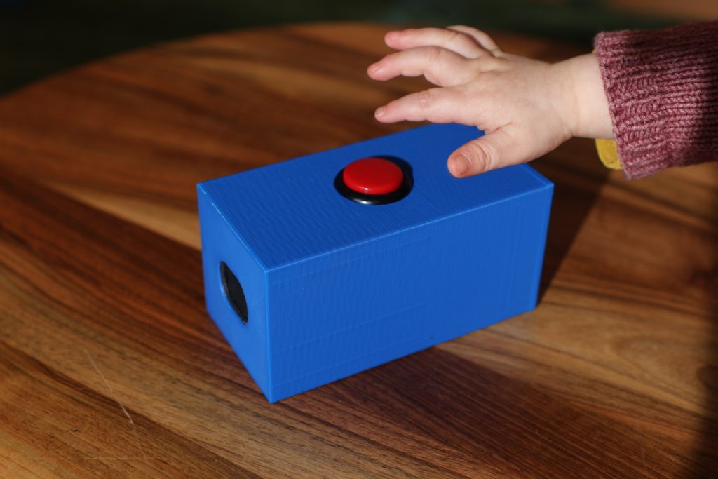
    The button is calling for action.

    The 3D models for the box are available on Printables. Here’s a list of parts:

    • Microcontroller WeAct Studio RP2040 – 2MB variant
    • Amplifier Max98357 I2S 3W Class D
    • Arcade button Sanwa 30mm
    • Speaker 4 Ohm 2W
    • Heat-set M4 threaded inserts
    • M4 screws
    • 5000mAh powerbank with USB-C port

    The code itself is pretty straightforward:

    import board
    import audiomp3
    import audiobusio
    import alarm
    
    audio = audiobusio.I2SOut(board.GP0, board.GP1, board.GP2)
    mp3 = audiomp3.MP3Decoder(open("song.mp3", "rb"))
    
    while True:
        audio.play(mp3)
        while audio.playing:
            pass
        
        print("Going to sleep")
        pin_alarm = alarm.pin.PinAlarm(pin=board.GP15, value=False, pull=True)
        alarm.light_sleep_until_alarms(pin_alarm)
        print("Waking up")
    

    I must say, my daughter really enjoys the toy; she loves pushing the button repeatedly. After a couple of weeks, she got tired of it, so I changed the song, and now the toy has regained her interest.
  • Battery-powered thermometer

    We have one indoor thermometer to tell us the temperature inside of our flat. It is actually a secondary function of an alarm clock, which is not particularly beautiful. I’ve decided to create my own, better looking and more accurate thermometer. I thought, how hard can it be?

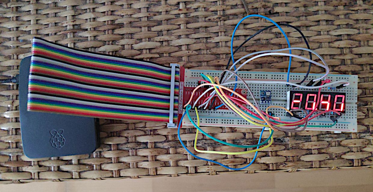
    First, I started by ordering a bunch of components and wanted to try them out on a Raspberry Pi 3. I put together a simple seven-segment display and a temperature sensor BMP180.

    Prototype using Raspberry Pi 3

    The temperature readings didn’t seem accurate to me and I found in the specification, that the reading can vary ±2°C. So I’ve decided to get a more accurate sensor, the MCP9808.

    Then came the time to make it battery powered. It makes little sense to run a Raspberry Pi 3 on a small battery, since it’s a single-board computer and takes a lot of power to operate. In order to save battery juice I needed to use a microcontroller instead. I chose an unofficial variant of the Raspberry Pi Pico, which has a USB-C port, the Weact Studio RP2040.

    I also opted to replace the display. The simple seven-segment display would require too many wires and I wanted to make my soldering job as easy as possible. So I got the TM1637, which is on a breakout board.

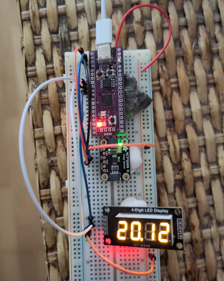
    Using microcontroller, not only the image is smaller.

    Now let’s get to programming in Thonny IDE. The biggest decision was whether to use MicroPython or CircuitPython. CircuitPython is a fork of MicroPython by Adafruit. I chose CircuitPython as Adafruit releases the MCP9808 library natively in CircuitPython and it’s the main library I need. There is a compatibility layer for MicroPython called Blinka, but it does not fit into the 2MB flash memory. Fortunately, there is a native CircuitPython firmware for Weact Studio RP2040 and a CircuitPython port of TM1637 library too.

    To optimise the energy usage, I set up a deep sleep for 60 seconds. Now it lasts 1 week on two AA rechargeable cells (each 2500 mAh). This is the final code:

    import busio
    import board
    import adafruit_mcp9808
    import time
    import TM1637
    import alarm
    
    CLK = board.GP7
    DIO = board.GP6
    display = TM1637.TM1637(CLK, DIO, 0)
    dead = False
    
    try:
        i2c = busio.I2C(board.GP1, board.GP0)
    
        t = adafruit_mcp9808.MCP9808(i2c)
    
        temp = t.temperature
        print(temp)
    
        integerPart = int(temp)
        decimalPart = int((temp % 1) * 100)
    
        display.numbers(integerPart, decimalPart)
    except:
        display.hex(0xdead)
        dead = True
    
    if not dead:
        time_alarm = alarm.time.TimeAlarm(monotonic_time=time.monotonic() + 60)
        alarm.exit_and_deep_sleep_until_alarms(time_alarm)
    

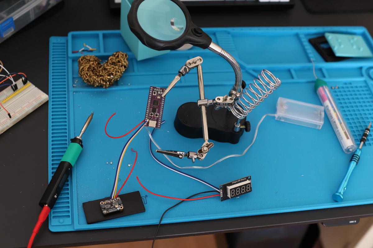
    I soldered everything together using the venerable Pinecil, which is such a pleasure to use.

    Soldering time

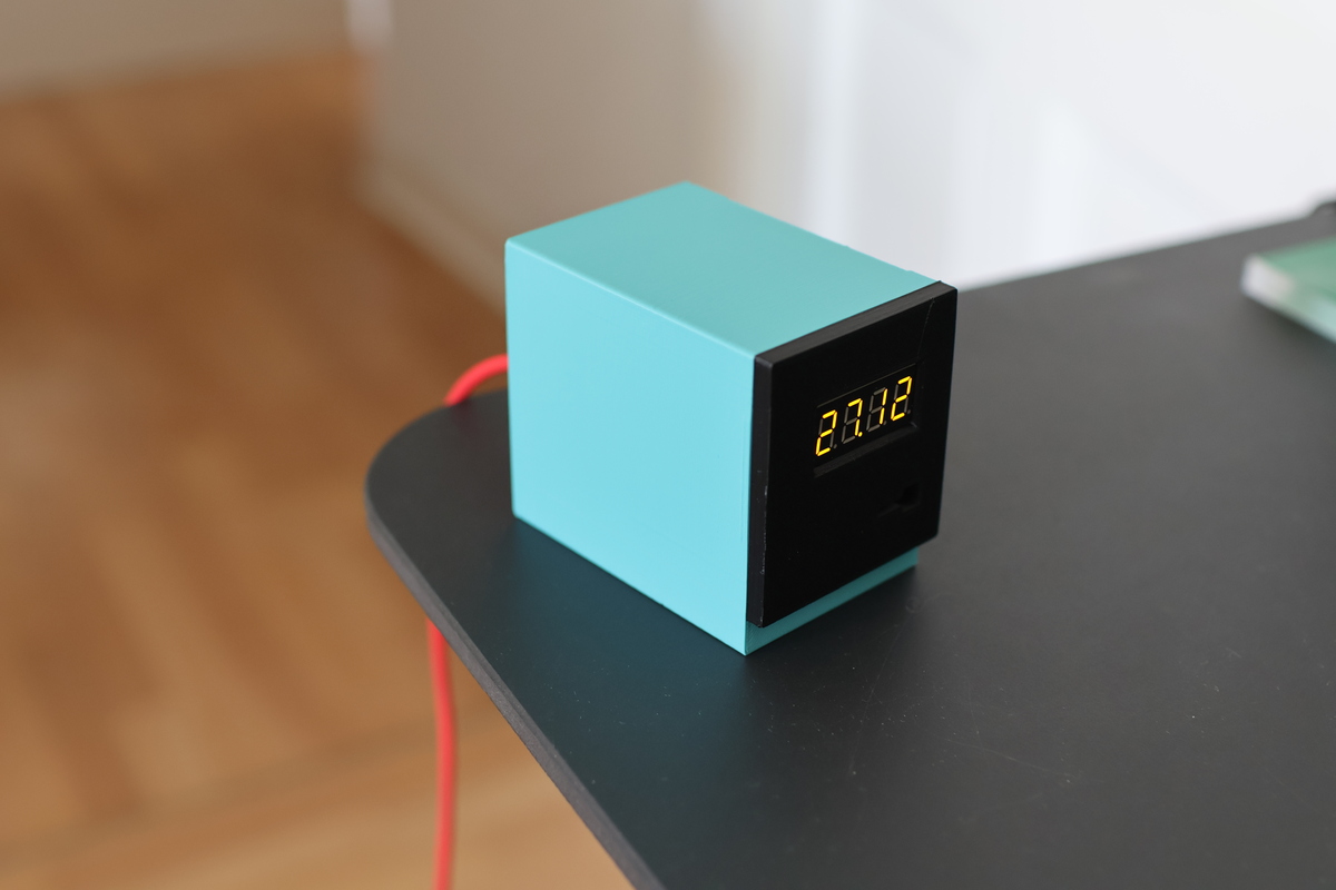
    Last step was to create a 3D enclosure for the whole thing. I started with a Macintosh-style enclosure, but needed to make it bigger and fit more components inside. After several iterations, I managed to design a fitting box in Blender, print it and assemble the thermometer.

    Voilà, the final product