
* Battery-powered thermometer
4. October 2023, Jakub Horák. Categorized as Electronics.
We have one indoor thermometer to tell us the temperature inside of our flat. It is actually a secondary function of an alarm clock, which is not particularly beautiful. I’ve decided to create my own, better looking and more accurate thermometer. I thought, how hard can it be?
First, I started by ordering a bunch of components and wanted to try them out on a Raspberry Pi 3. I put together a simple seven-segment display and a temperature sensor BMP180.
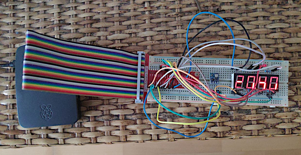
The temperature readings didn’t seem accurate to me and I found in the specification, that the reading can vary ±2°C. So I’ve decided to get a more accurate sensor, the MCP9808.
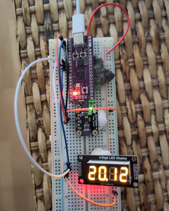
Then came the time to make it battery powered. It makes little sense to run a Raspberry Pi 3 on a small battery, since it’s a single-board computer and takes a lot of power to operate. In order to save battery juice I needed to use a microcontroller instead. I chose an unofficial variant of the Raspberry Pi Pico, which has a USB-C port, the Weact Studio RP2040.
I also opted to replace the display. The simple seven-segment display would require too many wires and I wanted to make my soldering job as easy as possible. So I got the TM1637, which is on a breakout board.
Now let’s get to programming in Thonny IDE. The biggest decision was whether to use MicroPython or CircuitPython. CircuitPython is a fork of MicroPython by Adafruit. I chose CircuitPython as Adafruit releases the MCP9808 library natively in CircuitPython and it’s the main library I need. There is a compatibility layer for MicroPython called Blinka, but it does not fit into the 2MB flash memory. Fortunately, there is a native CircuitPython firmware for Weact Studio RP2040 and a CircuitPython port of TM1637 library too.
To optimise the energy usage, I set up a deep sleep for 60 seconds. Now it lasts 1 week on two AA rechargeable cells (each 2500 mAh). This is the final code:
1 2 3 4 5 6 7 8 9 10 11 12 13 14 15 16 17 18 19 20 21 22 23 24 25 26 27 28 29 30 31 | import busio import board import adafruit_mcp9808 import time import TM1637 import alarm CLK = board.GP7 DIO = board.GP6 display = TM1637.TM1637(CLK, DIO, 0) dead = False try: i2c = busio.I2C(board.GP1, board.GP0) t = adafruit_mcp9808.MCP9808(i2c) temp = t.temperature print(temp) integerPart = int(temp) decimalPart = int((temp % 1) * 100) display.numbers(integerPart, decimalPart) except: display.hex(0xdead) dead = True if not dead: time_alarm = alarm.time.TimeAlarm(monotonic_time=time.monotonic() + 60) alarm.exit_and_deep_sleep_until_alarms(time_alarm) |
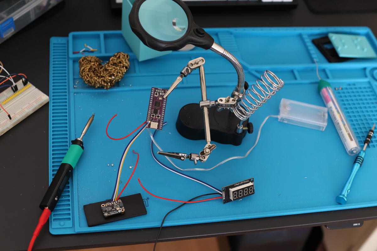
I soldered everything together using the venerable Pinecil, which is such a pleasure to use.
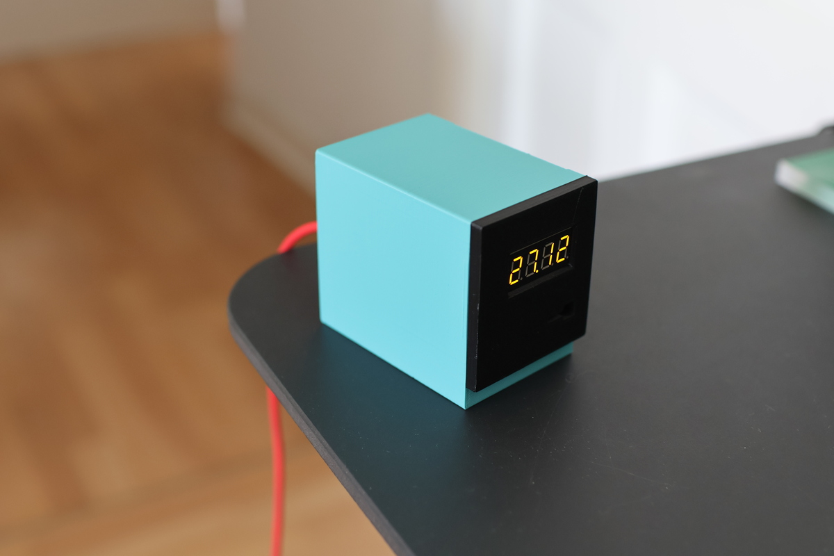
Last step was to create a 3D enclosure for the whole thing. I started with a Macintosh-style enclosure, but needed to make it bigger and fit more components inside. After several iterations, I managed to design a fitting box in Blender, print it and assemble the thermometer.
Leave a comment
Archives
- July 2025
- March 2024
- October 2023
- May 2020
- December 2018
- October 2018
- July 2017
- April 2017
- March 2017
- November 2016
- April 2016
- March 2016
- November 2014
- September 2014
- May 2014
- March 2014
- February 2014
- August 2013
- June 2013
- April 2012
- August 2011
- May 2011
- October 2010
- September 2010
- August 2010
- December 2009
- November 2009
- October 2009
- September 2009
- August 2009
- July 2009
- June 2009
- April 2009
- January 2009
- December 2008
- October 2008
- September 2008